

Struggling with dimensional variations or thread pitch errors on your conventional lathe? Machining high-precision rotary surfaces—such as shafts, sleeves, and discs—requires absolute mastery of the "touch method" for tool setting and precise gear ratio calculations.
This technical guide breaks down the operational workflows, troubleshooting for left and right-hand threading, and structural adjustments necessary to maximize your workshop's cutting efficiency and stop wasting raw materials.
Technical Operation: How to Establish High-Precision Cutting via the "Touch Method"?
In the machining of rotary surfaces—including internal/external cylindrical surfaces, conical surfaces, and end faces—the underlying logic of a conventional lathe remains constant: the spindle drives the workpiece to rotate at high speeds (primary movement), while the tool post moves the turning tool longitudinally or transversely (feed movement).
However, many novice machinists frequently encounter dimensional out-of-tolerance issues when transitioning from rough turning to fine turning. To eliminate this common headache, the operational standards for the touch method (tool setting) must be strictly regulated:
- Baseline Establishment: The tool tip must micro-contact the outer surface of the workpiece while the spindle is rotating in the forward direction. The exact moment a microscopic scratch appears is defined as the "absolute zero" for tool setting.
- Feed Rate Locking: Once the touch method is completed, immediately lock the depth of cut using the graduated dial or digital readout (DRO). During the rough turning phase, apply a large depth of cut to remove most of the blank allowance; for fine turning, micro-adjust the feed to guarantee the surface finish and tolerance range.
4. Technical Matrix: Threading "Bottlenecks" and Engineering Solutions
Threading is one of the most technically demanding operations on a conventional lathe. Overseas buyers frequently report that their shop operators are highly prone to cross-threading, tool breakage, or incorrect thread pitches when machining left- and right-hand threads.
Validated by the R&D team at MFG Machinery, we have distilled these real-world workshop failures into the following technical reference table to help your facility completely eliminate reject rates:
| Machining Flaws | Hidden Root Causes | Engineering Solutions |
|---|---|---|
| Pitch Mismatch | Incorrect calculation of the change gear ratio, or failure to strictly verify the multiple relationship between the target pitch and the lathe's lead screw. | The change gearbox must be disassembled to check the gear tooth count before starting. Ensure the spindle transmission ratio perfectly matches the preset lead screw feed. |
| Thread Distortion | The tool grinding angle does not match the thread profile, or the turning tool is not aligned with the workpiece's rotational center during setup. | Select high-rigidity indexable threading tools. If using brazed turning tools, strictly calibrate the center alignment using a thread gauge template. |
| Thread Stripping | Carelessly disengaging the half nut during the cutting stroke prevents the tool tip from returning to the original helical groove on the return pass. | Unless the thread pitch is an exact integral multiple of the lead screw pitch, never disengage the half nut before the full length is cut. The tool must be retracted using the spindle forward/reverse method. |
5. Structural Evolution: Evaluating Long-Term Reliability through Transmission Rigidity
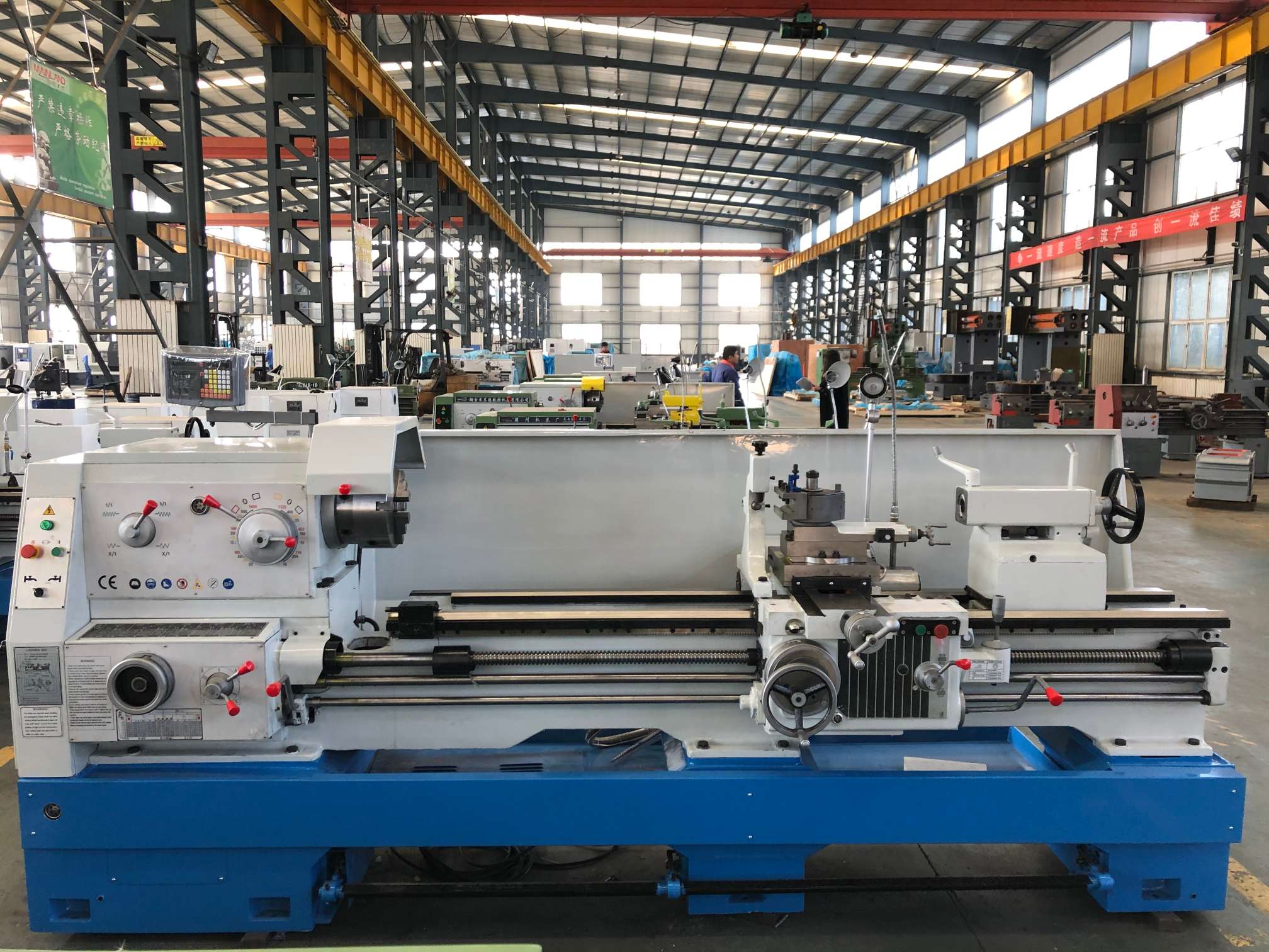
Beyond the machinist's craftsmanship, the rigid structure of the machine itself forms the foundation for heavy-duty cutting. Taking an industrial-grade standard lathe (such as the classic CA6140A architecture) as an example, its lower transmission system is driven by three core shafts: the Lead Screw, Feed Rod, and Control Rod.
- Lead Screw: Exclusively used for high-precision thread cutting, directly driving the half nut.
- Feed Rod: Used for daily external cylindrical and face turning to prevent premature wear of the lead screw.
- Control Rod: Centrally controls the forward/reverse rotation and emergency stop of the spindle.
This mechanical hard-linked architecture delivers a unique Return on Investment (ROI) in today’s industrial landscape. In harsh workshop environments where sensitive electronic components frequently crash due to extreme temperatures, heavy dust, or voltage fluctuations, the maintenance costs of CNC equipment can be astronomical.
Conversely, a conventional lathe featuring a heavy-duty cast iron bed and pure mechanical gear transmission demonstrates exceptional vibration resistance and delivers decades of high uptime.
6. Partner with a High-Quality Manufacturing Source: MFG Machinery
Relying solely on a beautifully polished technical manual won't completely eliminate dimensional errors on your shop floor; you need a heavy-duty machine tool embedded with precision DNA from the casting stage.
At MFG Machinery, we understand how vital shaft, sleeve, and disc components are to a busy fabrication facility. Our conventional lathes feature large spindle bores and multi-layered optimized structural designs.
They are not only easy to operate but also perfectly engineered to withstand heavy depths of cut under high-load conditions. Whether used for precision instrument machining or heavy machinery repair, our equipment provides uncompromised rigid support.
Looking to upgrade your workshop's cutting capacity or request detailed specifications for standard conventional lathes?
Contact our global technical support team today at info@mfg-machinery.com for a tailored technical solution and an exclusive quote!